Model #
6-082
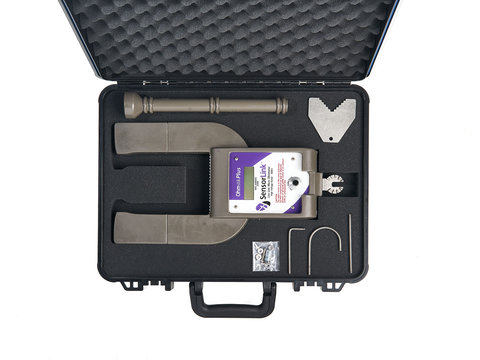
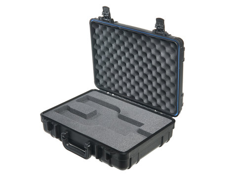
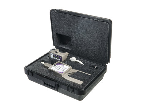
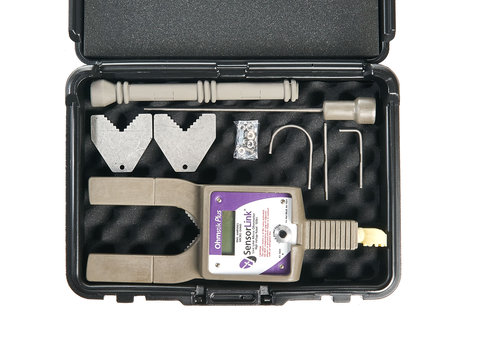
Multiple Reading Micro-Ohmmeter Kit
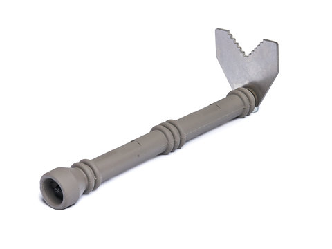
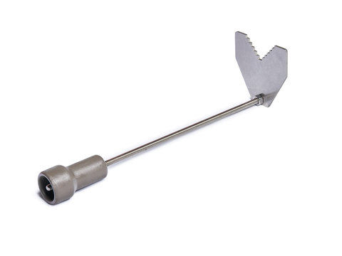
Ohmstik holds nine sets of readings up to 2500 µΩ, 1400A, 500KV, Standard 2.5” sensor opening
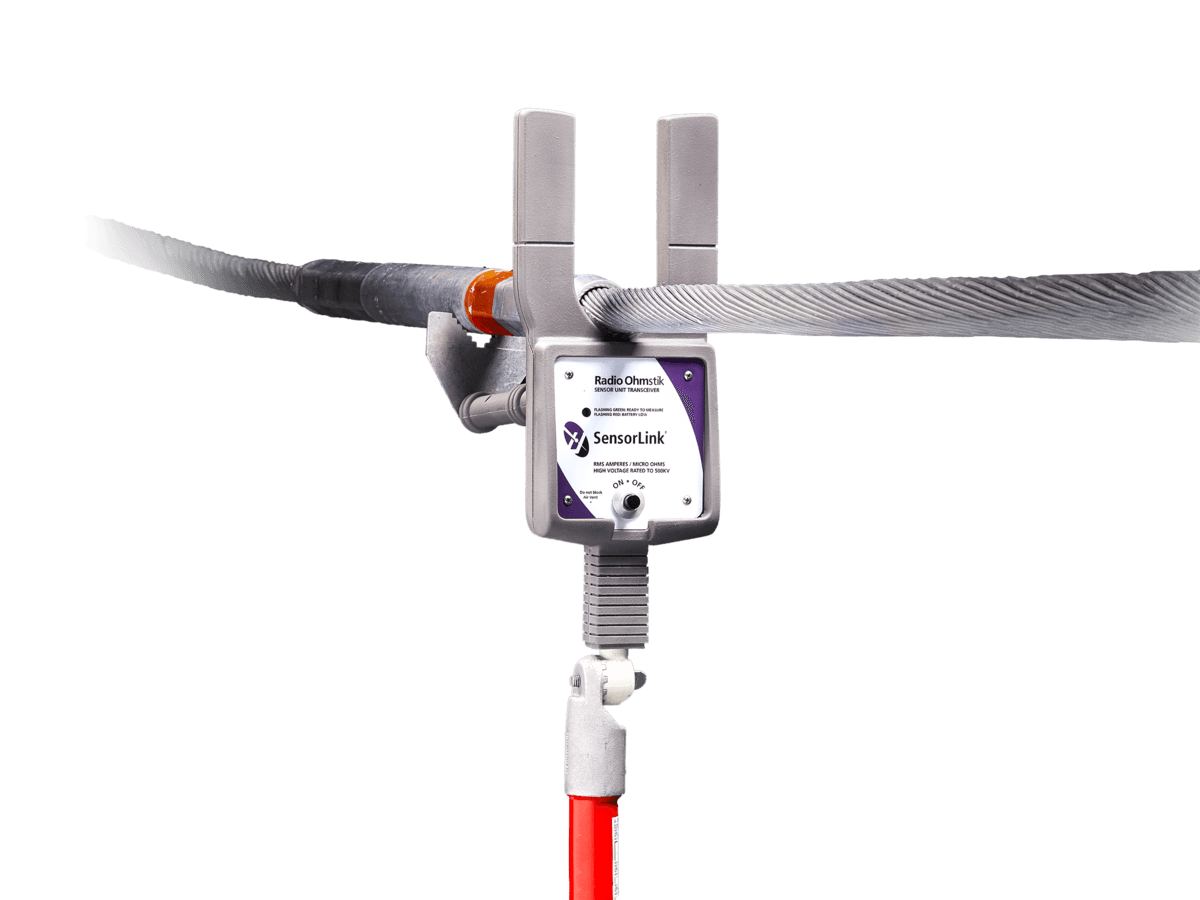
The Ohmstik Live-Line Micro Ohmmeter measures the micro-ohm resistance of conductors, connectors, splices and switching devices positioned directly on an energized, high voltage lines. This measurement is much more direct than infrared thermography, and is not subject to emissivity, weather, current loading, background, and other influences that cause infrared errors.
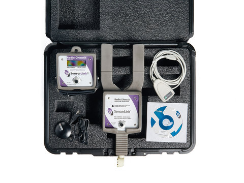
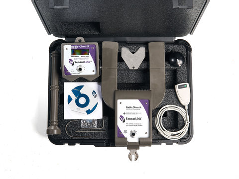
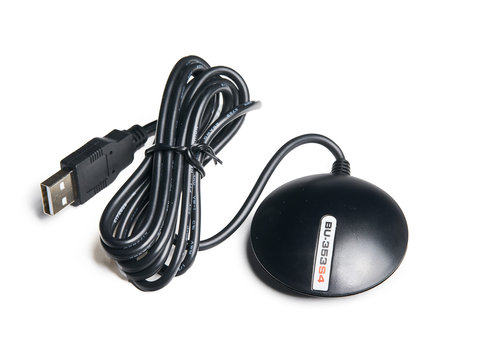
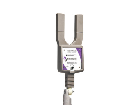
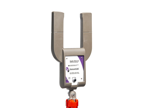
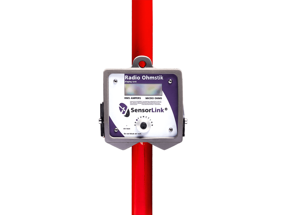
The Radio Ohmstik communicates the live-line measurements via radio to both a Remote Display Unit and a nearby computer. With the optional GPS device installed on the computer, all measurement, location, time and date data is automatically written and saved to a comma separated (CVS) file for future review and analysis.
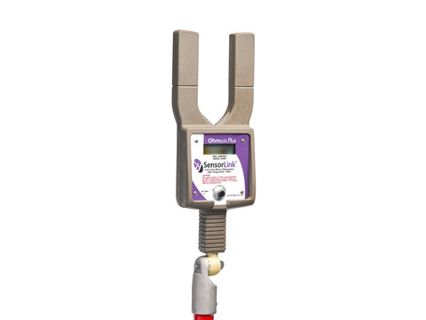
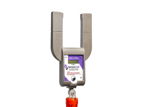
The Ohmstik Plus is designed to store up to nine sets of readings on the unit, with no external display. The ability to hold the multiple readings ends the need to raise and lower the hotstick after each measurement.
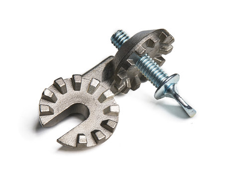
The Ohmstik calculates resistance by measuring the AC amperage in the line and the voltage drop due to the resistance of the line segment under test. Using the AC current in the line insures that realistic current distributions through the connection are being measured. The instrument is pressed against the splice or connector in such a manner that the connection under test is between the two electrodes. In a few seconds the instrument is removed from the line and the line amperage and resistance are displayed on the front panel LCD.
The Ohmstik can be used on almost any connection in a utility. Line splices can be checked after installation or after many years of service. Bolted terminals, taps, jumpers, and substation bus bars can be evaluated. Switches, fused disconnect, and normally open switches that have been open for long periods can be measured just after closing. Each of these connections can be measured quickly after installation, or surveyed after long service, to ensure proper resistance.
Time is not an “aging factor” for connectors. Deterioration is due to increases in resistance of the connection. Resistance can be produced by peaks of load and fault current that heat the interface, even if only temporarily or for a few cycles. Other factors of deterioration are the oxidation of the interfaces during thermal expansion and cooling, and by corrosion accelerated by moisture and chemicals that get between the strands. These influences will accelerate the deterioration of connectors that are not installed properly.
Research data on connector reliability indicates there will be further problems with unexpected failures than have occurred in the past. These failures come at a time when the need for reliability is essential. The Ohmstik gives utility engineers the data to predict a failure years in advance, allowing for replacement on a planned basis, before failure occurs.
Ohmstik Plus Specification |
Radio Ohmstik Specification |
Ohmstik Operators Manual |
Radio Ohmstik Operators Manual |