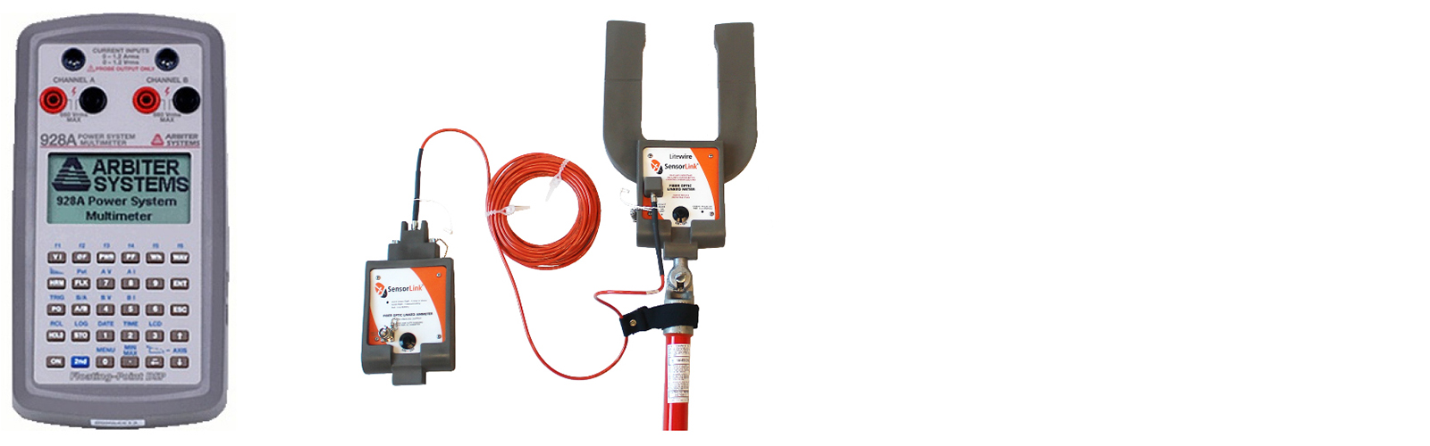
Arbiter Systems manufactures the Model 928A Power System Multi-meter. It has Floating-Point DSP™ Digital Signal Analysis and is an AC Power measurement instrument, providing outstanding performance and flexibility in a small, hand-held package. Not only does the Model 928A measure basic data and power quantities, but it also measures power quality including harmonics, flicker, sags, surges and interruptions. Incorporating a graphic LCD display, serial communications, real time clock and an unprecedented combination of features makes the Model 928A the ideal instrument for the power professional.
This meter is designed for use on low voltages, and additionally will measure higher voltages by using PTs and CTs. The SensorLink Litewire probes provide a portable PT and CT that easily adapt and have been evaluated in the Arbiter Systems’ Laboratories. These high voltage amp and volt probes are an efficient method for capturing waveforms on the distribution primary.
Follow the below instructions for connecting the Amp and Volt Litewire and configure the 928A for use.
To Connect a Volt Litewire and Arbiter 928A
Required Parts:
- Volt Litewire, SensorLink Part# 8-013 or 8-014
- Dual Banana Plug to BNC Connector, SensorLink Part# 7-011- CONN
- Coax Cable with BNC Connectors on each end
- Arbiter 928A Power System Multi-meter
Connecting:
- Connect the Dual Banana Plug to BNC Connector to Channel A of the Arbiter 928A. The Banana Plug has Red and Black plugs. Plug the Red lead into the Red terminal and the Black into the Black terminal.
- Connect the BNC Cable to the Analog output from the display of the Volt Litewire. And the other end of the BNC Cable to the BNC end of the Banana Plug.
To connect an Amp LiteWire to an Arbiter 928A
Required Parts:
- Amp Litewire SensorLink Part# 8-01502 XT or 8-01602
- Arbiter Current Input to BNC Cable Arbiter Part #CA0027200
- Pomona Banana-to-BNC(m) adaptor, Pomona Part #1296
- Arbiter 928A Power System Multimeter
Connecting:
- Connect the Arbiter Current Input to BNC Cable to Channel B of the Arbiter 928A in the Current Input connector on the Model 928A. Current inputs are at the top of the 928A.
- Connect the banana jacks at the other end of the Arbiter current cable t the banana-to-BNC adaptor. Plug the red banana plug of the current cable into th ered jack of the adaptor, and black banana plug into the black banana jack of the adaptor.
- Connect the BNC connector of the adaptor to the BNC connector of the analog output from the display of the Amp Litewire.
To Configure the Arbiter 928A to accept the Volt and Amp LiteWire Output
Select the Voltage and Current Channels:
Configure Channel A of the 928A to measure voltage and Channel B to measure current (See Pages 19-22 From the 928A’s User Manual).
- On the 928A, press [2nd] then [AV] to set Channel A to voltage
- On the 928A, press [2nd] then [BI] to set Channel B to current
Configure Voltage Ratio for Channel A on the 928A
Configure Channel A of the 928A to the correct ratio to read the voltage from the Volt Litewire probe. The correct value for the Volt Litwire probe is 10,000.
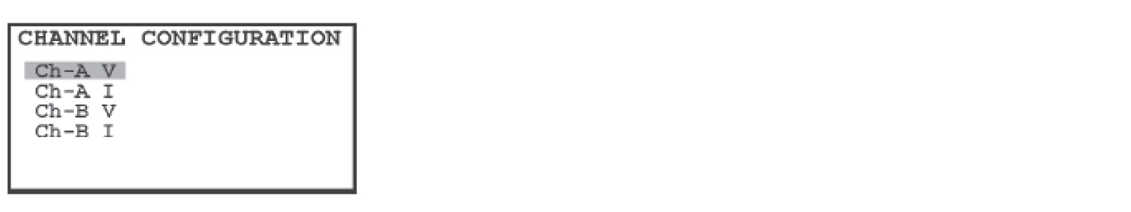
- On the 928A, pres keys [2nd] then [Menu] and ue the arrow keys to highlight “Ch-A, V” and press the [ENT] key.
- In the “Ch A VOLTAGE CONFIG” screen, the cursor should be resting on “INPUT RATIO”. To adjust the volage ratio, press the [ENT] key and the cursor will move to the ratio value. Now, use the numeric keys to type in the value “10000” and press the [ENT] key.
- To enter a phase offset, set the cursor to “PHASE OFFSET” and press the [ENT] key. Use the numeric keys to enter any phase offset and press the [ENT] key.
- To store these changes, highlight “<STOre And Exit>” and press the [ENT] key.
- Press the [ESC] key to go bakc to the main screen.
Configure Current Ratio for Channel B on the 928A
Configure Channel B on the 928A for the correct ratio to read the current from the Amp Litewire. The correct value for the Amp Litewire probe is 1,000.
- On the 928A, press keys [2nd] then [Menu] and use the arrow keys to highlight “Ch-B, I” and press the [ENT] key.
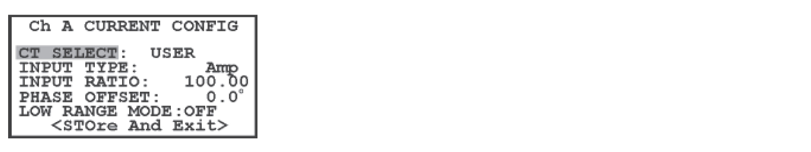
- In the “Ch B CURRENT CONFIG” screen, the cursor should be resting on the “CT SELECT”. Press the [ENT] key and choose the selection, “USER” and press the [ENT] key.
- In the “INPUT TYPE” selection, choose the value “Volt” and press the [ENT] key.
- In the “INPUT RATIO”selection, choose the value 1000 and press the [ENT] key.
- To enter a phase offset, set the cursor to “PHASE OFFSET” and press the [ENT] key. Use the numeric keys to enter any phase offset and press the [ENT] key.
- In the “LOW RANGE MODE” selection, set the value to “OFF”.
- To store these changes, highlight “<STOre And Exit>” and press the [ENT] key.
- Press the [ESC] key to go back to the main screen.